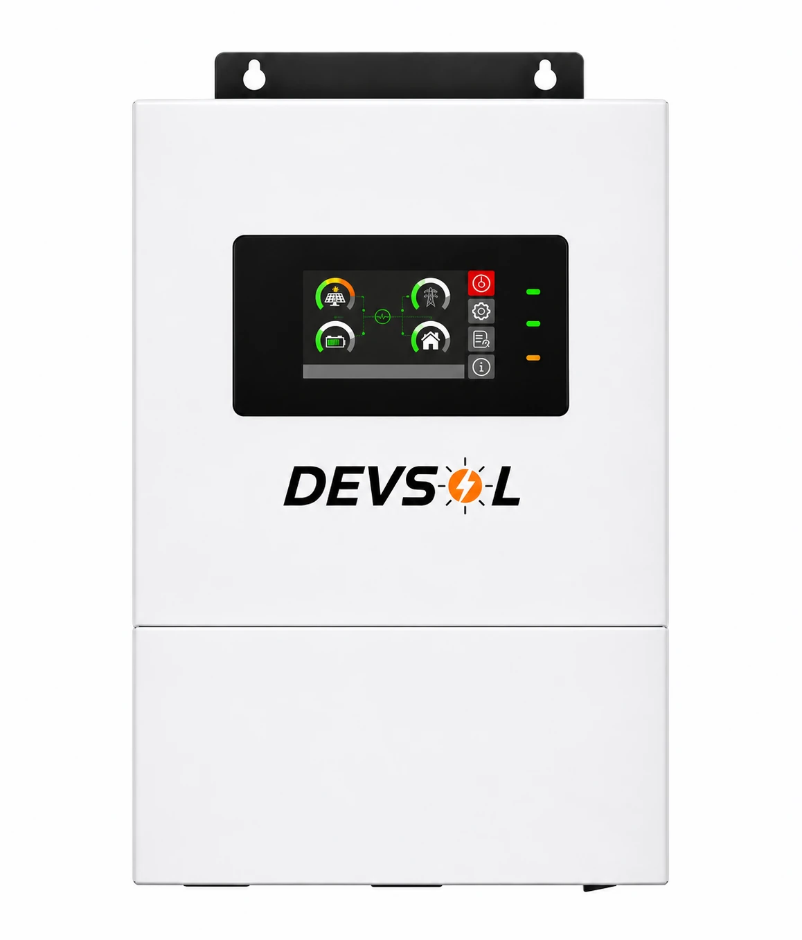
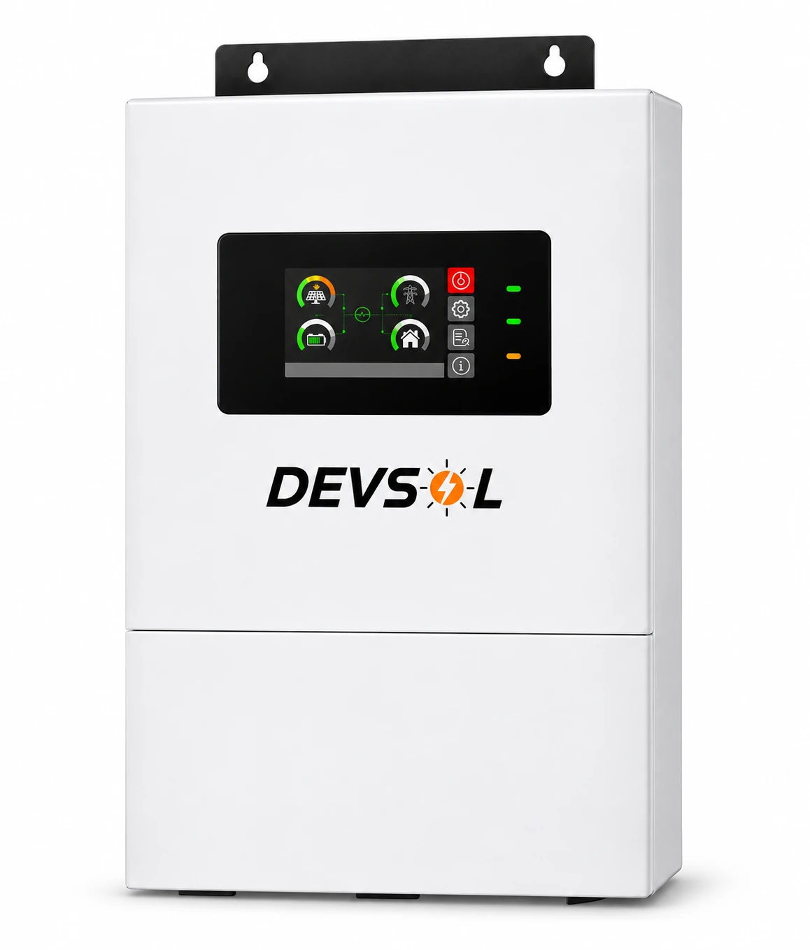
Unit price ₹51,200 + 5% GST (₹53,760 including GST).
A 24 V hybrid inverter for a 4 kW essential-load circuit
The Devsol DEV HYD 4KW supplies up to 4,000 W of rated pure sine wave AC output and accepts up to 5,000 W of solar PV on one MPPT. It fits homes and small businesses that want to build around a compatible 24 V battery bank and a single solar string. Two managed AC outputs let the installer prioritize essential loads. Plan around appliances that actually run together, then check the starting demand of compressors, pumps and motors.
The single MPPT suits modules with a common orientation and similar shade exposure. Its specified tracking window starts at 60 V DC and extends to 450 V DC. The PV input accepts up to 27 A within the inverter's other PV limits. The 60 V figure is the lower tracking boundary. Confirm the startup threshold for the supplied unit when designing a short string.
DC battery system and real backup capacity
Electrical and environmental specifications
| Parameter | Rating |
|---|
| Rated output | 4,000 W / 4,000 VA |
|---|
| Surge apparent power | 8,000 VA |
|---|
| Nominal battery voltage | 24 V DC |
|---|
| Supported battery types | Compatible lithium and lead-acid |
|---|
| Maximum PV array power | 5,000 W |
|---|
| PV trackers and strings | 1 MPPT / 1 string |
|---|
| Maximum PV input current | 27 A |
|---|
| MPPT operating range | 60–450 V DC |
|---|
| Maximum PV array open-circuit voltage | 500 V DC |
|---|
| Nominal AC input | 230 V AC |
|---|
| Selectable AC input range | 170–280 V computer mode, 90–280 V appliance mode |
|---|
| AC input frequency | 50/60 Hz, auto sensing |
|---|
| Battery-mode AC regulation | 230 V AC ±5% |
|---|
| Output frequency and waveform | 50/60 Hz, pure sine wave |
|---|
| AC output circuits | Two outputs with load management, within total inverter rating |
|---|
| Peak inverter efficiency | 93% published peak |
|---|
| Typical transfer time | 10 ms computer mode, 20 ms appliance mode |
|---|
| Maximum solar charging current | 120 A |
|---|
| Maximum AC charging current | 100 A |
|---|
| Maximum combined charging current | 120 A |
|---|
| Cabinet ingress protection | IP54 |
|---|
| Operating ambient temperature | −10°C to +50°C |
|---|
| Relative humidity | 5–95%, non-condensing |
|---|
| Altitude | Derating at 2,000 m |
|---|
| Monitoring and service interfaces | RS232 and USB. Optional Wi-Fi |
|---|
| Battery communication | CAN / RS485 for compatible BMS |
|---|
| Parallel option | Up to six matching units with supported configuration and accessories |
|---|
| Safety standards referenced | EN/IEC 62109-1 and EN/IEC 62109-2 |
|---|
The 24 V architecture can suit sites with an existing compatible lithium or lead-acid bank. At 4,000 W and nominal 24 V, the ideal DC current is about 167 A. At an assumed 90% conversion efficiency it is about 185 A. Lower loaded battery voltage raises current further. Size the battery, BMS, DC disconnect, fuse, busbar and cables for the installation's continuous and surge currents. Follow the product manual, applicable installation requirements and battery limits.
For example, a 25.6 V, 100 Ah lithium bank stores 2.56 kWh nominal. At 80% usable capacity and an illustrative 90% battery-to-AC conversion efficiency, roughly 1.84 kWh reaches the load. That is about 2.3 hours at 800 W under those assumptions. A 100 A battery BMS would limit this example bank to roughly 2.56 kW on the DC side at nominal voltage. Full inverter output therefore requires a battery bank capable of more current. The 120 A maximum charging rating is a charge-side limit.
For lead-acid, size usable capacity around the battery maker's depth of discharge and discharge-rate curves. For lithium, confirm the exact BMS protocol, supported wiring and current limits. Select the charge profile for the actual pack. Configured charging should respect the battery maker's charge-current limit and temperature limits.
Solar string design example
Assume a 550 W module with 49.5 V open-circuit voltage (Voc), 41 V operating voltage (Vmp), 13 A operating current and a Voc temperature coefficient of −0.28%/°C. Eight in series yield 4,400 W nominal and 328 V Vmp at standard test conditions. At a design cell temperature of −5°C, estimated string Voc is about 429 V. This example is within the 5,000 W PV ceiling, 500 V absolute Voc limit and 60–450 V MPPT window under the stated assumptions.
The installer should recalculate with the module nameplate, the site's minimum expected temperature and the highest expected module temperature. Hot module voltage falls and cold open-circuit voltage rises. Check the module's short-circuit current and the inverter's permissible short-circuit current for the final design. Series-connected modules add voltage. Parallel connections add current and require a separate current, protection and connector check.
AC input, transfer and load planning
The nominal AC input is 230 V. Computer mode accepts 170–280 V and lists a 10 ms transfer time. Appliance mode accepts 90–280 V and lists 20 ms. These input acceptance windows describe the AC source the inverter can use. Grid export depends on the approved model and site interconnection. Check sensitive loads for transfer tolerance.
The listed 8,000 VA surge helps evaluate short starting loads. Use measured or manufacturer-rated starting VA and surge duration when matching a motor or compressor. At a power factor of 1, 4,000 W at 230 V corresponds to roughly 17.4 A. That number describes the nominal load, while actual protective devices and wiring must be selected for the installation.
Where the 4 kW model is the best fit
Choose it for a single-orientation array, a 24 V battery bank that can support the intended current, and essential circuits within the 4 kW rating. Examples include lighting, fans, networking, refrigeration and a small office load after checking startup demand. Solar and grid can serve supported battery-less operation where configured. Specify battery storage when the design calls for dependable backup through grid failures and variable solar input.
Commissioning checklist
- List simultaneous running watts and startup VA. Assign loads to the essential and secondary circuits.
- Verify the battery chemistry, compatible BMS link, charge profile, continuous current and transient current.
- Calculate cold Voc, hot Vmp and string current. Verify DC isolation, overcurrent protection, earthing and cable routing.
- Install in a sheltered, ventilated location within the specified ambient range. Leave the clearances in the installation manual.
- Record transfer tests, protective settings and each output's behavior on grid, PV and battery before handover.
Frequently asked questions
Which battery voltage does the Devsol 4 kW model use?
It uses a nominal 24 V DC battery bank. Compatible lithium and lead-acid banks can be configured.
How much solar PV can the Devsol 4 kW model take?
It accepts up to 5,000 W on one MPPT, within 60–450 V tracking voltage, 500 V maximum array Voc and 27 A maximum PV input current.
Will it run an air conditioner?
Compare its starting VA, running power and concurrent loads with the 4,000 W continuous and 8,000 VA surge ratings. Confirm the required surge duration and battery current.
Does it work without a battery?
It supports a configured solar-plus-grid battery-less mode. Specify a compatible battery for a dependable outage backup design.
Can I install it outdoors?
Use a sheltered, ventilated installation that meets the IP54 enclosure requirements and manufacturer clearances.
Can it handle two different roof orientations?
It has one tracker. For independent roof orientations, the Devsol DEV HYD 6KW Dual MPPT provides two trackers.
How fast does it transfer?
The specified transfer time is 10 ms in computer mode and 20 ms in appliance mode.
Gallery shows Devsol product renders.
Compare the Devsol 6 kW, 48 V Dual MPPT inverter and see the hybrid inverter buying guide for load, battery and roof layout guidance.
For product and warranty support, email info@devsolenergy.com.